")
How do I know if it’s time to ventilate my office?
Do I need to nap, or is the air quality making me dizzy?
How can we ensure the best air quality conditions with so many people in one room?
The questions above provided an excellent opportunity for us to launch a side project where we could explore the uncharted territory of software. This blog post is designed as a companion to our last one, which covered getting started with firmware as a hardware engineer. It’s an example of a simple project that you could use to get familiar with the basics of firmware design, but there are a variety of other projects that would be appropriate – follow what interests you!
Before we dig into the details, we’ve got to refine the specific requirements of our project;
Lay down the requirements.
Before starting the design, we must have a list of features we expect from the final device. It’s common practice to do this by laying out a PRD (Product Requirements Document). Often these seperate each requirements into categories based on their priority. Having a document like this keeps everybody on the same page and helps the team(s) pick the best design path. There’s lots to say aout PRDs that we can’t fit into this blog post, so we’ll leave our more in-depth thoughts for a dedicated blog post in the future. For now, if you’d like to know more about the purpose of a PRD this blog post would be a good start.
After consideration, the priorities and requirements for our environmental monitor were as follows:
- Accuracy and cost were to be prioritised. – aesthetics were not of significant concern.
- Power consumption requirements were negligible – the device would sit in the office, so the power supply was not a concern.
- A highly intuitive user interface – the purpose of this device was to keep a log of the environmental conditions in our office. A fully automated device that does not require any input/action from the user, simply outputs information in a straightforward way.
- Hassle free. Maintenance (both firmware and HW) must be kept to a minimum – again, we sought to prioritise simplicity of interaction for the user. Low upkeep requirements contribute towards this goal.
Pick your environmental sensor.
We have added URLs to PCBAs that feature each chip instead of SMT parts.
There are two options for carbon dioxide sensors: one that effectively measures CO2 concentration and one that estimates CO2 from other gasses.
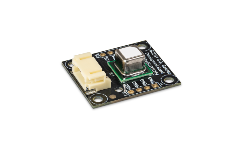
The SCD30 and SCD40(41) from Sensirion are two of the top options for this kind of application.
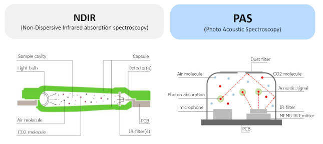
They use two techniques (NDIR and PAS) to measure the CO2 concentration. The specifics are outside the scope of this post, but follow the links if you want to dig deeper.
These sensors can measure temperature, humidity and CO2 only. They’re on the high-end scale of things, and as such, they’re pricey compared to other alternatives.
On average, they also have a bulkier form factor, making them more difficult to integrate into small IoT device enclosures.

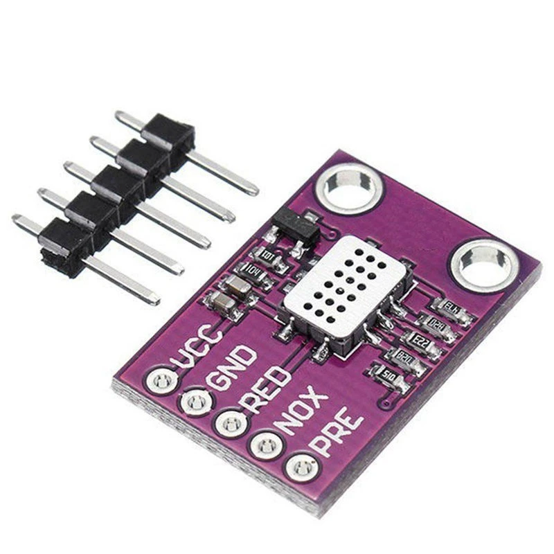
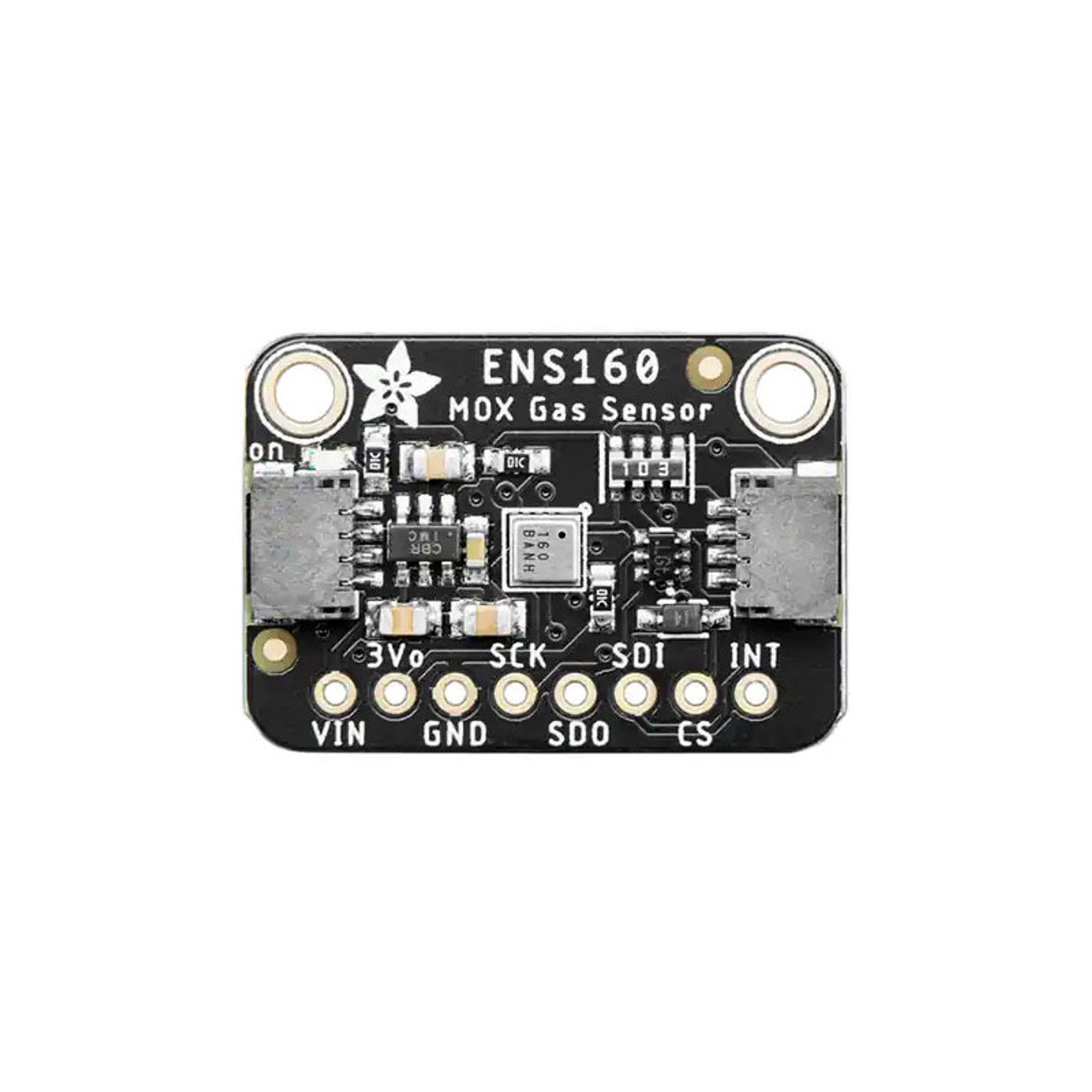
SGP30, MiCS-4514, ENS160 use different technologies and one or more algorithms to calculate an eCO2 value (equivalent Carbon Dioxide).
These sensors can calculate environment variables like Temperature, Humidity, eCO2, TVOC, AQI, CO, NO2. They’re generally cheaper than their counterpart mentioned above and often available in a smaller form factor.
Our choice
Let’s cut to the chase: we did test the low-end sensors, and the results were not good.
- Data was often a mere index of the air quality rather than a numerical value of CO2, CO, or NO2.
- Cheaper sensors require calibration on their first run and usually every month. This makes them cumbersome, needing a calibration device and additional maintenance time.
- Even with proper calibration, you can expect a tolerance of +/-15% of the calculated value(s).
Due to our disappointing results from the lower end sensors, we opted for the SCD41. The Sensirion folks did an impressive job with automatic calibration algorithms. This was a critical aspect of our decision, as our PRD laid out a requirements of keeping maintenance to a minimum.
For your reference, this sensor’s accuracy is 5% of the CO2 readings. A great addition to the above is that SCD41 is easy to interface with most MCU via its I2C bus, and Sensirion provides some well-made libraries to handle all the hard work and let you operate this device with just a few lines of code.
Select the display
Our next big decision was the display to use. Based on the PRD, our device shall have a simple and intuitive interface. This could be a display that shows temperature, humidity, and CO2 in a carousel mode.
HDMI displays require a powerful MCU like a Raspberry Pi or above. These displays are not standard in sizes below 4 inches and are more suitable for high-quality animations and videos.
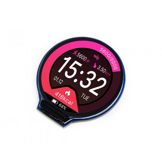
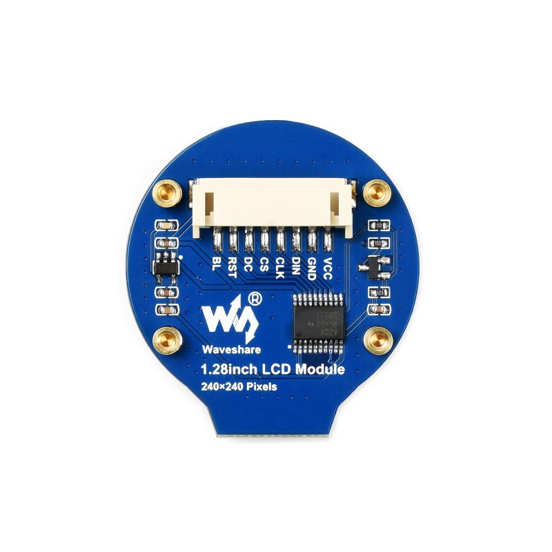
An SPI display was a better option for this project. A downside of these displays is the increased coding effort. On the bright side, they have smaller form factors and lower price tags. Their SPI interface is also directly compatible with ESP32 and Arduino MCUs. Our choice was a rounded 1.28” display from Waveshare. Its shape made it easy to have the layout we wanted: numbers in the centre surrounded by a coloured ring used as a gauge for the CO2 level.
This decision will be highly dependant on your specific needs for your project – again, we see the immense value of a PRD laying this out in clear terms.
Select the MCU
For convenience, we will add URLs to modules instead of single chips. Modules like soldering are easier to interface with an MCU and do not require EE effort.
We needed an MCU capable of handling one I2C and one SPI peripheral. WiFi connection was required to upload data to the cloud while no battery charging and management circuitry was needed.
For this reason, we decided to go for an ESP32. Most modules that use this chip would do for this project and even the older ESP8266 could handle this application.
If you want to learn more about selecting the best microcontroller for your project, look at our blog post about “How to get started on firmware”. This decision could be heavily influence by your experience with specific architecture or programming languages.
Choose the enclosure


You can find all sorts of enclosures on the market. Some may protect better against water, white while others can focus on aesthetics. We intended to keep things simple. That’s why we used a tiny paperboard box that could fit the display, the sensor, and the ESP32, along with the wires connected.
We ended up with a raw but neat, eco-friendly device – perfect given our specific PRD.
Connect everything

Jumper wires are good enough as we’re not dealing with high-speed signals for this project. They’re widely available, cheap, and convenient for debugging while you tailor and test the code to make it do what you want.
Flash your code to the device!
Our project’s complete code is now available on a public Github repository. Before flashing the device, follow the initial hardware steps outlined in the included readme file.
We used ThingSpeak as our cloud platform to host our data, but there are a variety of options available.
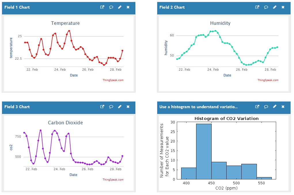
You can create a channel for your device by following the guide at this link. ThingSpeak is free for personal use and allows you to customise your channel with charts and indicators, and you can even run MATLAB analysis on your data or export it for other uses. Once you flash the code on your ESP32 and everything works as expected, you can power your device from any wall charger or USB port without needing it to be connected to a computer.
Have a look at the public channel for our own device that has been up and running in our office for 3 months already, recording temperature, humidity and CO2 every 10 minutes!